Arc Flash Analysis
Why Arc Flash Analysis?
In short: personnel safety.
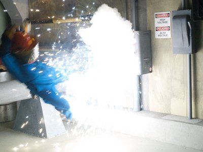
Any time energized electrical equipment is examined, adjusted, serviced or maintained; the risk of injury is present.
Depending on the amount of energy present, serious injury or death can result without proper protective equipment (PPE) and training.
Through engineering analysis, the appropriate PPE can be identified, greatly reducing the potential for injury.
-

-
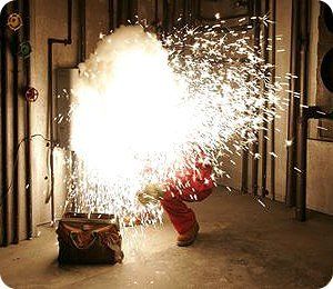
Photo By: John Doe
-
-
Photo By: John Doe


What Regulations Apply to Arc Flash?
OSHA 29 CFR 1910.132 (d) as follows:
1910.132(d)(1) The employer shall assess the workplace to determine if hazards are present, or are likely to be present, which necessitate the use of personal protective equipment (PPE). If such hazards are present, or likely to be present, the employer shall:
- 1910.132(d)(1)(i) Select, and have each affected employee use, the types of PPE that will protect the affected employee from the hazards identified in the hazard assessment.
- 1910.132(d)(1)(ii) Communicate selection decisions to each affected employee; and,
- 1910.132(d)(1)(iii) Select PPE that properly fits each affected employee.
- 1910.132(d)(2) The employer shall verify that the required workplace hazard
assessment has been performed through a written certification that identifies the workplace evaluated; the person certifying that the evaluation has been performed; the date(s) of the hazard assessment; and, which identifies the document as a certification of hazard assessment.
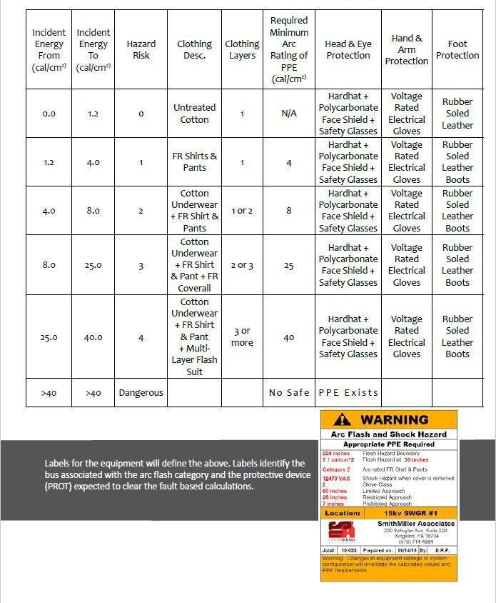
NFPA 70E-2011 Article 110.16 requires Arc-Flash Hazard Warnings be placed on electrical equipment likely to require examination, adjustment, servicing or maintenance while energized. Without completing a study the proper PPE cannot be determined.
The purpose for the arc flash study is to determine the available incident energy and the protective clothing (PPE) requirement for persons working on live equipment. An Arc Flash study can only be conducted in conjunction with a short circuit and coordination
study to obtain clearing times of over-current protective devices. This will calculate the proper PPE, based on the arcing fault current levels and protective device clearing times per IEEE 1584-2004, to comply with OSHA 1910.132 d and 1910.335.
Working Distance Equipment Type kV
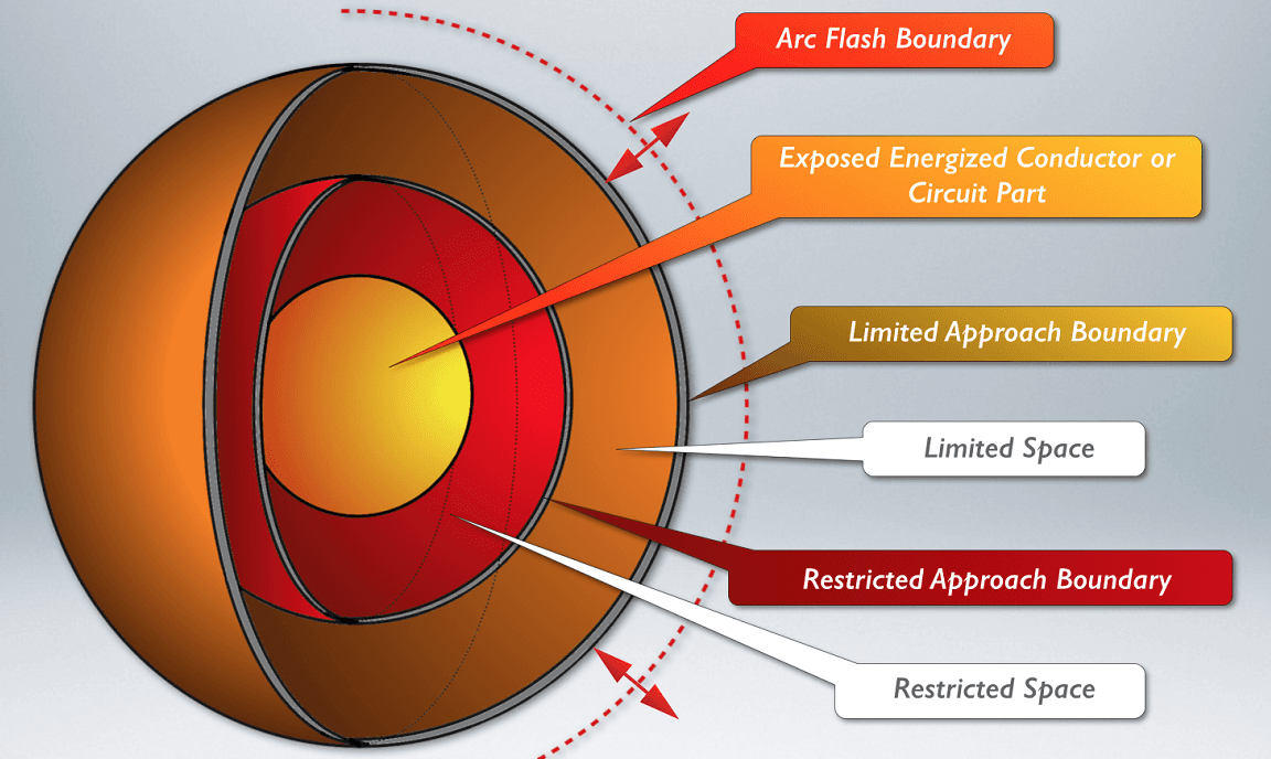
Flash Protection Boundary from NFPA 70E.
BASIS FOR CALCULATIONS:
An Arc Flash Hazard Analysis was performed based on the results of the short circuit study. IEEE 1584 calculations were performed as this is the industry standard. The IEEE 1584 calculation method calculates both a low tolerance
and maximum arcing fault. The calculations are compared and the worst case is represented in the arc flash results and identified with a N3. In most cases the low tolerance results in a longer trip time and the incident energy is higher. The
results are shown in the attached tables within this section.
The Arc Flash Hazard analysis establishes the flash protection boundary, hazard category and proper PPE class of clothing if working on a live bus. It should be noted that this PPE level is calculated per NFPA 70E/IEEE 1584 to reduce burns to
second degree or below.
The calculation parameters used for this study utilize a line side report with load side contributions. This method assumes the fault is cleared by the nearest upstream device. This means that panels equipped with a main circuit breaker may
experience an arcing fault on the line side of the main breaker while it is closed thus receiving the fault contributions also on the load side by that panel; in which case only the upstream device will be capable of tripping and clearing the
fault. This assumption is intended to produce conservation results and therefore cover the case where faults originating in such equipment may propagate to the line side of the local main circuit breaker.
It is important to note that the Arc Flash Hazard Analysis applies to the recommended protective device setting shown in this study only. Adjustments to the circuit breaker time dial or replacement of fuses with unlike kinds may change
the Arc Flash category of the bus therefore requiring that updated calculations are performed and possible change in category levels and PPE may apply. The results of this study assume that protective devices used for the evaluation are
properly maintained and are in working order and will operate within specified tolerances to clear faults from the system. Non-functioning over-current protective devices or devices with setting other than those specified in this study can
allow arcing faults to persist for longer than normal, producing a very significant arc flash beyond the results of the calculations presented in this report. Protection from arc flash hazards can best be provided by working only on circuits or
equipment that has been placed in a de-re-energized electrically safe working condition.